
What Is Inspection?
Earthing inspection verifies by measurement whether the protective earthing of an electrical installation performs its function. Earthing offers fault current a low-resistance path so that the protective device trips; when the resistance rises, that protection no longer works.
Why Is It Done?
The aim is to prevent the risk of electric shock and to ensure that protective devices can trip within the defined time when a fault occurs. Earth resistance changes over time: soil moisture, corrosion and loosening connections all raise the value.
Which Equipment Is Covered?
- Building and facility protective earthing
- Machine and equipment earthing
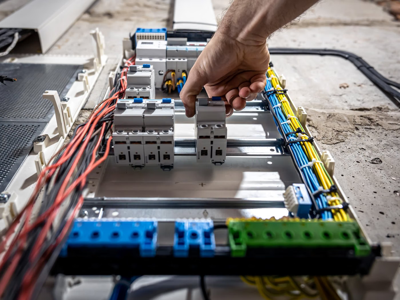
- Electrical panels and distribution systems
- Generator and transformer earthing
- Construction sites and temporary installations
Legal Basis and Interval
For electrical installations and protective systems the inspection interval follows the applicable electrical installation legislation and the risk class of the environment. In high-risk installations — explosive atmospheres, damp locations, construction sites — the interval is markedly shorter. Every substantial alteration to the installation calls for a new inspection.
Scope of Inspection
- Earth electrode and earth resistance measurement
- Continuity of the protective conductor (PE)
- Equipotential bonding connections
- Earthing bar and connection terminals
- Adequacy of conductor cross-sections
- Corrosion and loosening at connection points
- Conformity of the earthing system with the installation type (TN, TT, IT)
- Accessibility of the test link and measurement points
Related Standards
- ISO/IEC 17020
- IEC 60364-6
- IEC 62305-3
- IEC 60364-5-54
- EN 50522
Method and Equipment
- Earth resistance tester (three- and four-terminal method)
- Clamp-on earth resistance tester
- Continuity tester (low-resistance ohmmeter)
- Soil resistivity measuring equipment
- Calibrated multimeter
Inspection Process
- 1Preliminary Information and PlanningThe single-line diagram, panel list, protective device data and installed capacity are collected; measurement points are defined.
- 2Visual InspectionPanel layout, conductor cross-sections, tightness of connections, labelling and protection against contact are checked visually.
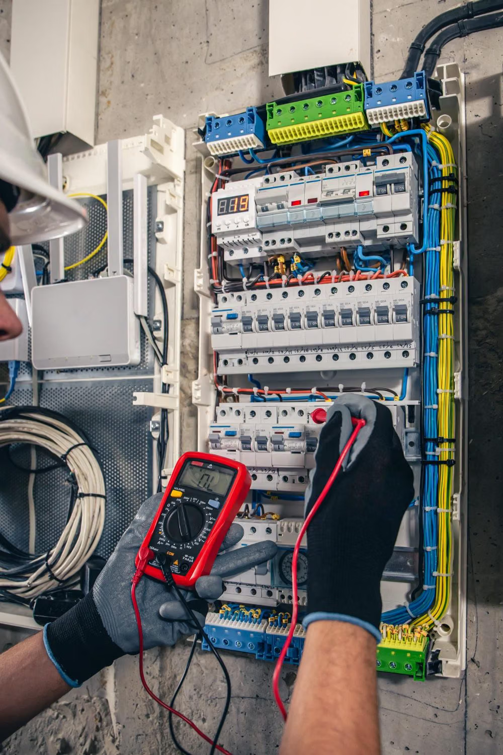
- 3MeasurementsUsing instruments with traceable calibration, earth resistance, insulation resistance, continuity, loop impedance and residual-current device trip values are measured.
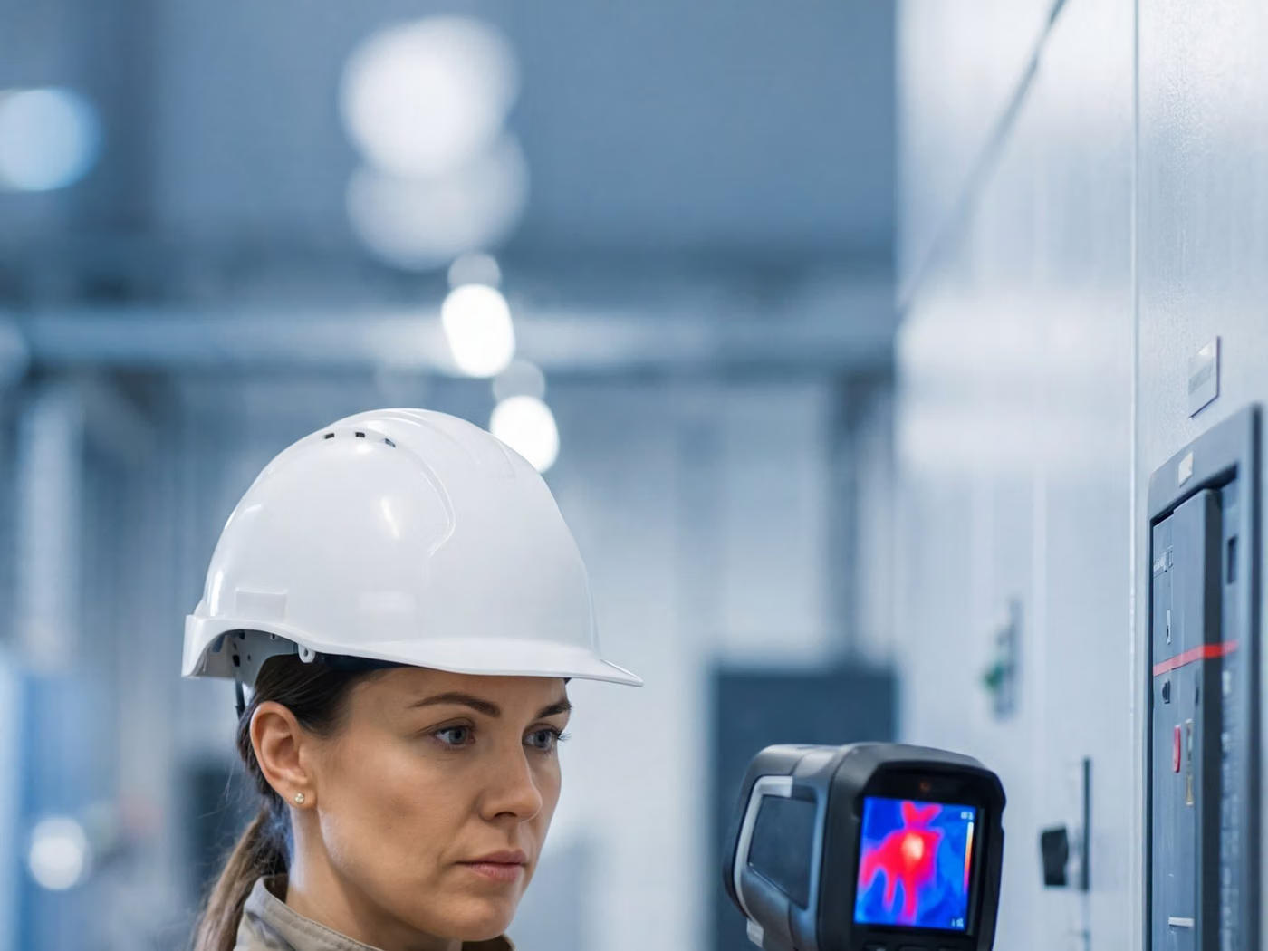
- 4Thermographic SurveyAbnormal heating at connections under load is surveyed with an infrared camera and graded against the reference temperature difference.
- 5AssessmentMeasured values are compared with the limits set by the relevant standard and by the design values of the installation.
- 6ReportingMeasurement tables, thermal images and the list of nonconformities are compiled into a report; corrective actions are proposed in order of priority.
Nonconformities
A measured earth resistance above the limit calculated for the installation means the protective device will not trip in a fault, and is a serious finding that must be corrected. A break in the continuity of the protective conductor carries the same weight.
Inspection Report
- Details of the inspection body and the inspection personnel
- Identification of the installation and scope of inspection
- Measuring instruments used and their calibration data
- Tables of measurement points and measured values
- Thermal images and assessment of temperature difference
- Comparison with limit values
- List of nonconformities and their priority order
- Conclusion and the next inspection date
Accreditation
Inspection activities are carried out under ISO/IEC 17020, which requires the impartiality of the inspection body, the competence of its personnel and the validity of the inspection methods. Under the impartiality rule, a party that maintains or repairs an item of equipment cannot carry out the independent inspection of that same equipment. EUROLAB holds internationally recognised accreditation under ISO/IEC 17020, granted by accreditation bodies that are signatories to the ILAC mutual recognition arrangement; because accredited scope is defined per inspection type, it is confirmed in writing at the quotation stage.
Scope and authorisationsRelated Inspections

Frequently Asked Questions
What should the earth resistance value be, in ohms?
There is no single universal value. The limit is calculated based on the installation's earthing system (TN, TT, IT), the protective device's tripping current and the permitted touch voltage. This is why the report includes not only the measured value but also the calculated limit.
Does taking the measurement after rain change the result?
Yes. Soil moisture noticeably lowers the resistance; a measurement taken after rainfall does not reflect the true worst-case condition. For this reason, the measurement conditions and the season are recorded in the report.
Why does the report state the calibration of the measuring instruments?
The result of an electrical inspection is not an observation but a measured value. For the measurement to be valid, the instrument must have been calibrated traceably; a measured value without calibration data cannot be defended.
Is the installation de-energised during the inspection?
Some measurements are made de-energised (insulation resistance, continuity) and others energised (loop impedance, residual current device, thermography). The inspection is therefore planned with both a short outage window and a period of operation under load.