
What Is Inspection?
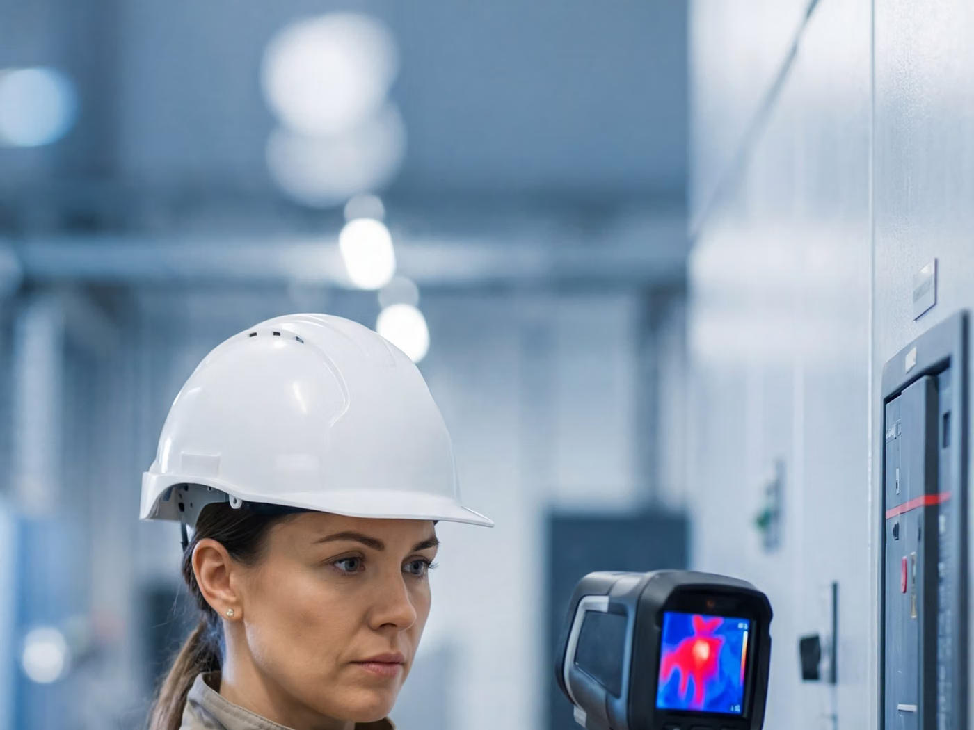
Thermographic inspection scans electrical equipment under load with an infrared camera to find abnormally hot spots. The method is contactless and applied while the plant is running, so it gives warning before a failure without stopping production.
Why Is It Done?
The aim is to find loose connections, overloading, unbalanced phase loading and degrading components before they turn into a failure. A significant share of electrical fires starts from a hot spot that thermography could have shown months earlier.
Which Equipment Is Covered?
- Electrical distribution panels and switchyards
- Transformer and generator connections
- Motor and drive panels
- Cable terminations and busbar systems
- Bearing and coupling overheating in mechanical equipment
Legal Basis and Interval
For electrical installations and protective systems the inspection interval follows the applicable electrical installation legislation and the risk class of the environment. In high-risk installations — explosive atmospheres, damp locations, construction sites — the interval is markedly shorter. Every substantial alteration to the installation calls for a new inspection.
Scope of Inspection
- Connection terminals and busbar joints
- Fuse, circuit breaker and contactor connections
- Phase balance and load distribution
- Cable terminations and transition points
- Transformer and reactor temperature distribution
- Motor frame and bearing temperatures
- Temperature difference from a reference (equivalent) point on the same circuit
- Recording of ambient temperature and load percentage
Related Standards
- ISO/IEC 17020
- ISO 18434-1
- IEC 62446-3
- ASTM E1934
Method and Equipment
- Calibrated infrared thermal camera
- Clamp meter (for load measurement)
- Ambient temperature and humidity meter
- Emissivity reference tapes
Inspection Process
- 1Preliminary Information and PlanningThe single-line diagram, panel list, protective device data and installed capacity are collected; measurement points are defined.
- 2Visual InspectionPanel layout, conductor cross-sections, tightness of connections, labelling and protection against contact are checked visually.
- 3MeasurementsUsing instruments with traceable calibration, earth resistance, insulation resistance, continuity, loop impedance and residual-current device trip values are measured.
- 4Thermographic SurveyAbnormal heating at connections under load is surveyed with an infrared camera and graded against the reference temperature difference.
- 5AssessmentMeasured values are compared with the limits set by the relevant standard and by the design values of the installation.
- 6ReportingMeasurement tables, thermal images and the list of nonconformities are compiled into a report; corrective actions are proposed in order of priority.
Nonconformities
Findings are graded from the temperature difference (ΔT) between the hot spot and a reference point and from the percentage of load. High ΔT values are classified as requiring urgent action, low values as items to be corrected at planned maintenance. The grading thresholds follow the specification applied.
Inspection Report
- Details of the inspection body and the inspection personnel
- Identification of the installation and scope of inspection
- Measuring instruments used and their calibration data
- Tables of measurement points and measured values
- Thermal images and assessment of temperature difference
- Comparison with limit values
- List of nonconformities and their priority order
- Conclusion and the next inspection date
Accreditation
Inspection activities are carried out under ISO/IEC 17020, which requires the impartiality of the inspection body, the competence of its personnel and the validity of the inspection methods. Under the impartiality rule, a party that maintains or repairs an item of equipment cannot carry out the independent inspection of that same equipment. EUROLAB holds internationally recognised accreditation under ISO/IEC 17020, granted by accreditation bodies that are signatories to the ILAC mutual recognition arrangement; because accredited scope is defined per inspection type, it is confirmed in writing at the quotation stage.
Scope and authorisationsRelated Inspections
Frequently Asked Questions
Why is the scan carried out under load?
Heating arises from current. In an unloaded or lightly loaded system, even a faulty connection appears at a normal temperature. For this reason, the load percentage during the scan is recorded; a result obtained at low load does not represent the worst case.
Can the scan be carried out without opening the panel cover?
A closed cover blocks infrared radiation and hides the hot spot inside. For this reason, the scan is carried out either with the cover opened under appropriate safety measures, or through infrared-transparent windows.
Why does the report state the calibration of the measuring instruments?
The result of an electrical inspection is not an observation but a measured value. For the measurement to be valid, the instrument must have been calibrated traceably; a measured value without calibration data cannot be defended.
Is the installation de-energised during the inspection?
Some measurements are made de-energised (insulation resistance, continuity) and others energised (loop impedance, residual current device, thermography). The inspection is therefore planned with both a short outage window and a period of operation under load.