
What Is Failure Analysis?
Damage analysis is the systematic examination of a damaged component by visual inspection, fracture surface (fractography), metallography, chemical analysis, hardness and mechanical tests; This is the study in which the damage mechanism and root cause are determined.
Purpose of Failure Analysis
The purpose is to determine the failure mechanism (fatigue, overload, corrosion, stress corrosion cracking, creep, brittle fracture) and root cause, defining the corrective action that will prevent recurrence.
Which Products Is Failure Analysis Applied To?
- Fractured machine elements
- Failed welded joints
- Corroded pipe and equipment
- Prematurely failed fasteners
In Which Sectors Is Failure Analysis Used?
Standards Related to Failure Analysis
- ASTM E2332 (fractography guide)
- ASTM E3 / E407 (metallography)
- ISO 6892 / ISO 148 (mechanical tests)
- ASTM E415 / ISO 11885 (chemical analysis)
Failure Analysis Conditions
- Step 1
- Document collection: service conditions, loading history, manufacturing records
- Step 2
- Non-destructive visual and stereo examination; the fracture surface is preserved
- Step 3
- Fractography (stereo and SEM), metallography, chemical analysis
- Step 4
- Mechanical and hardness tests; stress analysis if required
Equipment for Failure Analysis
- Stereo microscope and digital imaging
- Scanning electron microscope (SEM/EDS)
- Metallography preparation line
- Chemical-analysis and mechanical-test equipment
Sample Requirements for Failure Analysis
- The fracture surface must not be cleaned or brought into contact with itself
- The part must be sent as is, together with all broken pieces
- Service conditions and failure history must be documented
- An undamaged reference part is useful for comparison
Duration of Failure Analysis
2–6 weeks, depending on scope.
Failure Analysis Procedure
- 1Failure history and service conditions are gathered.
- 2The part is examined non-destructively and documented.
- 3The fracture surface is examined fractographically.
- 4Metallography, chemical analysis and mechanical tests are carried out.
- 5The failure mechanism is determined.
- 6Root cause and corrective-action recommendations are reported.
Failure Analysis Acceptance Criteria
Failure analysis is not a conformity test; its result is not pass/fail but the determined failure mechanism and root cause.
Evaluation of Results
Cleaning the fracture surface or bringing pieces into contact with each other destroys the most valuable evidence. Jumping to a root cause from a single finding is a common mistake; the mechanism must be supported by multiple independent findings.
Failure Analysis Report
- Failure history and service conditions
- Visual and fractographic findings
- Metallographic, chemical and mechanical results
- Failure mechanism
- Root-cause assessment and recommendations
Accreditation
EUROLAB holds internationally recognised accreditation obtained from accreditation bodies party to the IAF and ILAC multilateral recognition arrangements, under ISO/IEC 17025 for laboratory testing, ISO/IEC 17020 for inspection and surveillance, and ISO/IEC 17021-1 and ISO/IEC 17065 for system and product certification. This chain ensures the reports and certificates issued are accepted worldwide.
Whether this test can be offered within accredited scope depends on your product and the standard applied; since accreditation is method-based, the scope is confirmed in writing at the quotation stage.
Scope and authorisationsRelated Regulations
- Product standards and manufacturing specifications
Metal and Metallurgy Testing — What Does This Testing Field Cover?
The section below describes the field that the Failure Analysis test belongs to; the conditions and acceptance criteria of this particular test are given in the sections above. The scope specific to your product is confirmed in writing at the quotation stage.
Metal and metallurgical testing determines the load a metal or a welded joint can carry, how it fails and what its internal structure looks like. The output of this family is often not about the product itself but about the identity of the MATERIAL: is the steel really of the declared grade, does the weld seam deliver the strength the design assumes, does the casting contain an unacceptable internal defect?
The practical importance of the field comes from the fact that a metal part rarely fails gradually. A plastic part deforms, ages, cracks and usually gives warning. A weld seam or a fastener, by contrast, often breaks without warning — especially where fatigue and brittle fracture are involved. That is why in fields such as pressure equipment, lifting gear, structural steel and pipelines, material testing is a requirement of REGULATION rather than of design.
The family brings together three groups of methods, and each answers a different question. Mechanical tests quantify how the material behaves under load. Non-destructive examination looks for defects without damaging the part. Metallography and chemical analysis explain why the material behaves the way it does — through grain structure, phase distribution, inclusion content and alloy composition.
The acceptance criterion for these tests almost never comes from the test standard, and this is the key to understanding the field. The test standard says how the measurement is to be made; the acceptable values come from the product standard, the material grade or the fabrication code. ISO 6892-1 tells you how to run a tensile test; EN 10025 tells you what yield strength that steel must deliver. When reading a report, the product standard it was assessed against is essential.
Sampling is an inseparable part of the result in this field. Two specimens taken from the same heat may give different values depending on the direction and location they were taken from; in rolled products, specimens parallel and perpendicular to the rolling direction produce different results. Product standards therefore also govern sampling location and orientation, and the report must document this.
Method groups in this field
Mechanical tests
Tensile, compression, bending, notch impact (Charpy), hardness (Brinell, Vickers, Rockwell), fatigue, creep and fracture toughness. These give the behaviour of the material under load in numerical form.
Non-destructive examination
Radiography, ultrasonic examination, penetrant, magnetic particle and visual examination. It looks for surface and internal defects without damaging the part and is an indispensable step in welded fabrication.
Metallography
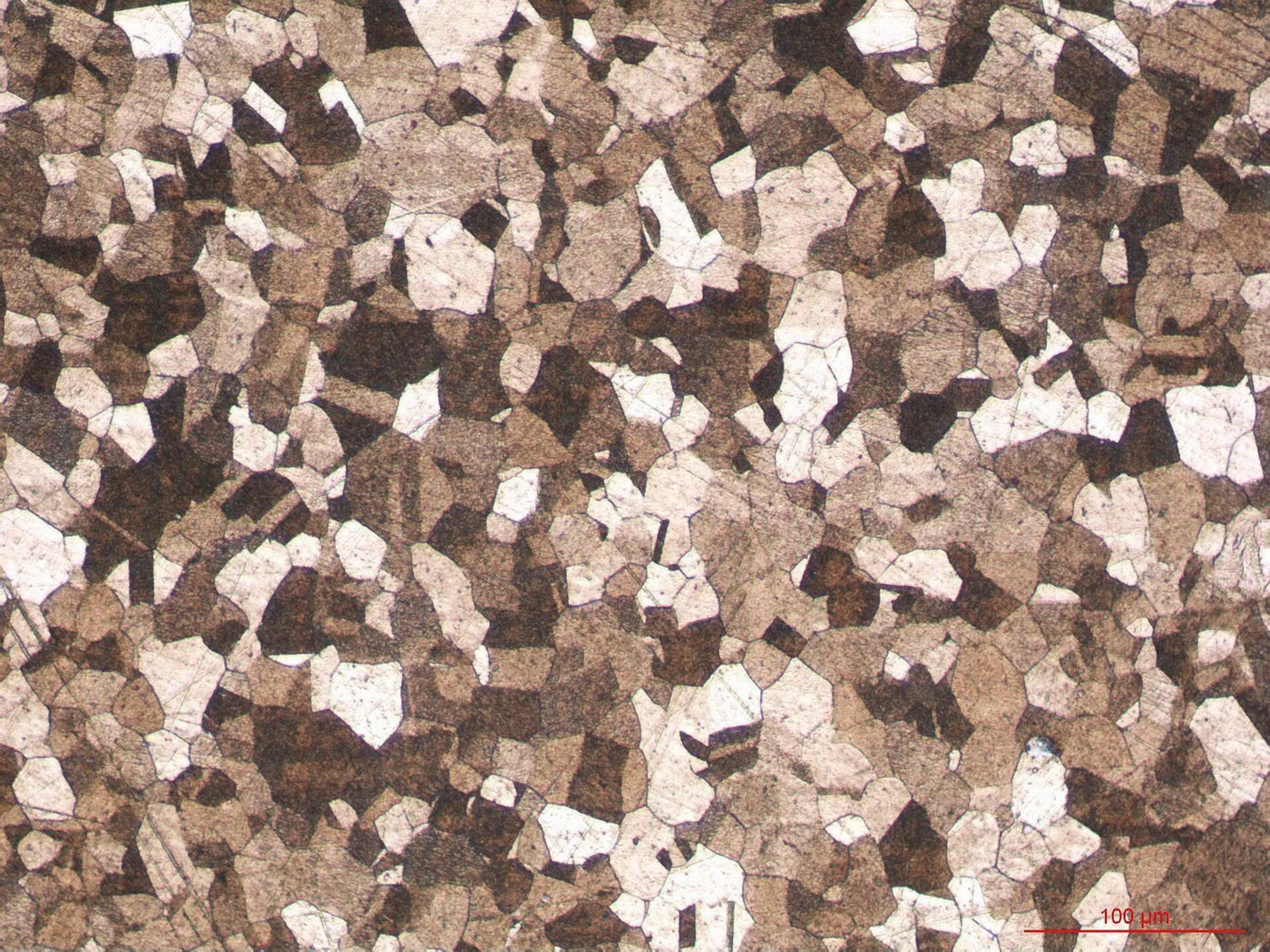
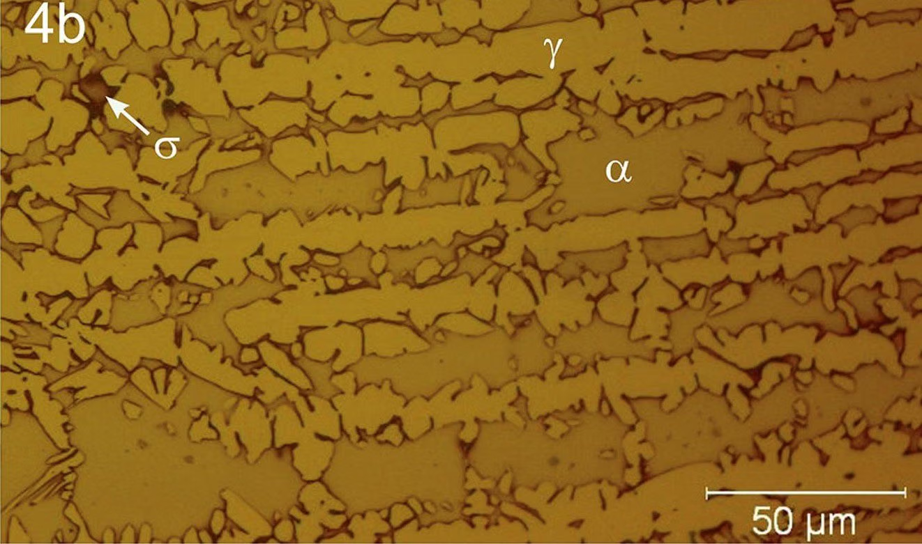
Specimen preparation, etching and microscopic examination. Grain size, phase distribution, inclusion content, case depth and the weld heat-affected zone are assessed.
Chemical analysis
Alloy composition is verified by optical emission spectrometry and wet chemistry; confirmation of the material grade runs through this step.
Corrosion behaviour
Salt spray, pitting and crevice corrosion and intergranular corrosion tests. In stainless steels these can indicate the quality of the heat treatment.
Commonly confused in this field
- A material certificate (such as EN 10204 3.1) is not a test report; it is the manufacturer's declaration. In critical applications independent verification is carried out, and the two must not be confused.
- ASTM and ISO tensile tests measure the same quantities but use different specimen geometries; the results are not treated as directly equivalent, and whichever the specification calls for is the one applied.
- Conversion tables between hardness and strength are APPROXIMATE. Calculating yield strength from hardness is not sufficient evidence for material acceptance.
- In non-destructive examination, "no defect found" does not mean there is no defect; defects below the detection limit of the method may be present. The report must state the method applied and the sensitivity level.
- A weld seam passing does not show that the welder or the procedure is qualified; these are separate processes.
Which decisions these results support
- Verifying the material certificate and accepting incoming material
- Approving welded fabrication; welder and procedure qualification
- Manufacturing control of pressure equipment and structural components
- Failure analysis and determining the root cause of field damage
- Verifying heat treatment and surface treatment processes
Related Tests



Frequently Asked Questions About Failure Analysis
Should I clean the part before sending it for failure analysis?
No. The fracture surface must not be cleaned, brushed, or the broken pieces brought into contact with each other; these actions destroy the most important evidence showing the failure mechanism. The part must be sent as is, dry and protected.