
What Is Four-Point Bending?
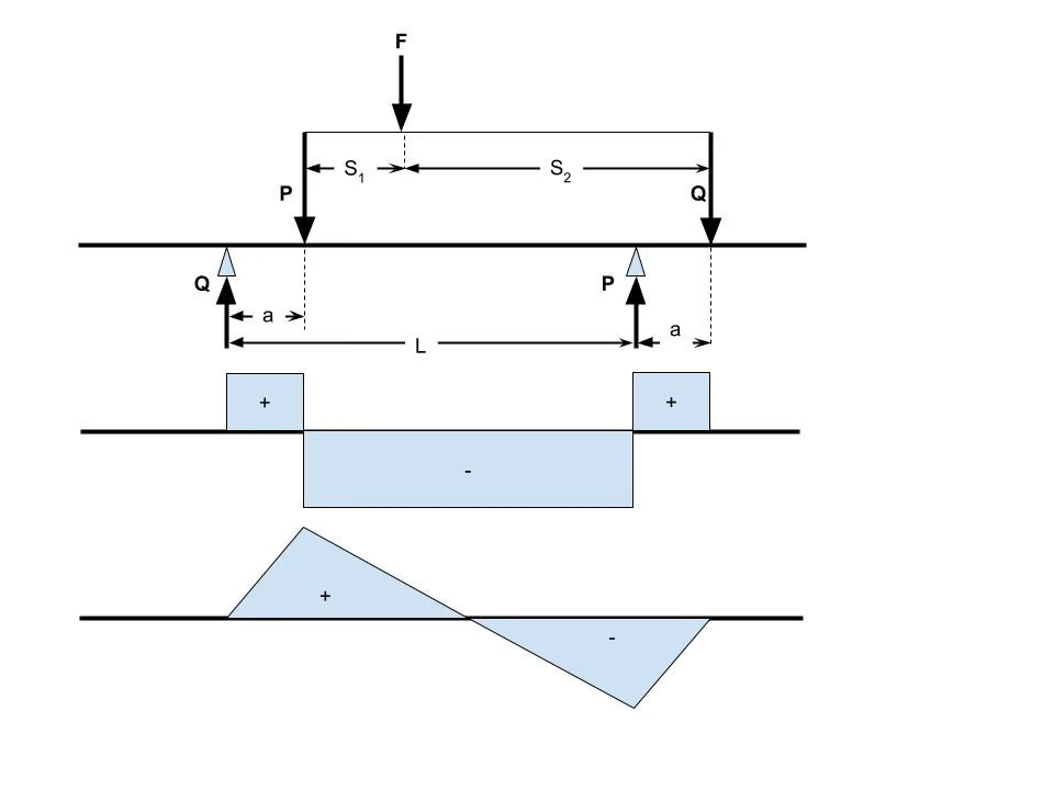
In the four-point bending test, the specimen rests on two supports and is pressed by two separate loading noses. The bending moment is constant in the region between the loading noses; shear force is zero there. Fracture therefore occurs at the location of the specimen's weakest defect.
Purpose of Four-Point Bending
The purpose is to determine the material's flexural strength in a way that also reflects the defect distribution. For defect-sensitive materials such as ceramics and composites, this approach gives a more realistic strength than the three-point test.
Which Products Is Four-Point Bending Applied To?
- Advanced technical ceramic parts
- Fibre-reinforced composite panels
- Concrete and mortar beams
- Wood and wood-based structural elements
- Welded and coated metal specimens
In Which Sectors Is Four-Point Bending Used?
Standards Related to Four-Point Bending
- ASTM D6272 (four-point bending of plastics)
- EN 843-1 (advanced technical ceramics)
- ISO 14125 (composites — including the four-point setup)
- EN 12390-5 (concrete — flexural strength)
Four-Point Bending Conditions
- Setup
- Two supports and two loading noses; loading span from the standard
- Moment region
- Constant moment between the loading noses, zero shear
- Test speed
- The speed given by the standard for the material class
- Quantities measured
- Flexural strength, flexural modulus, breaking load
Equipment for Four-Point Bending
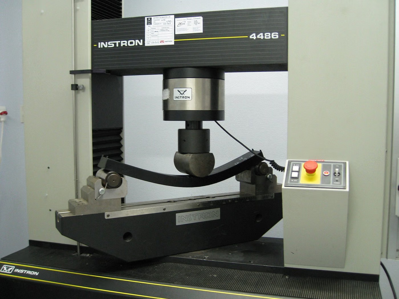
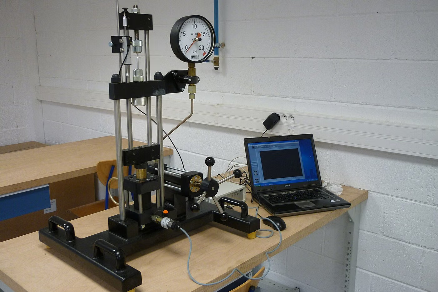
- Universal tension-compression machine
- Four-point bend fixture (self-aligning)
- Load cell and deflection gauge
- Specimen measurement equipment
Sample Requirements for Four-Point Bending
- Specimen surfaces must be machined per the standard, with edges chamfered.
- For ceramic specimens, the surface grinding direction affects the result and must be reported.
- The number of specimens must be sufficient to allow statistical evaluation.
- Specimen orientation and production direction must be recorded.
Duration of Four-Point Bending
A single specimen's test takes minutes. Because the defect distribution requires many specimens, total duration depends on the number of specimens.
Four-Point Bending Procedure
- 1The specimen is measured and its surface condition recorded.
- 2Support and loading spans are set per the standard.
- 3The specimen is centred on the fixture.
- 4Loading is applied at the defined speed.
- 5Load and deflection are recorded; the moment of fracture is determined.
- 6Flexural strength is calculated and the fracture location is noted.
Four-Point Bending Acceptance Criteria
The method standard defines how the test is performed, not what the result should be. The acceptance limit comes from the material standard, the product specification or the customer's technical drawing; this page therefore gives no numerical limit.
Evaluation of Results
For defect-sensitive materials, results are assessed with distribution parameters (e.g. the Weibull modulus) rather than a single average. Fracture is expected between the loading noses; fractures occurring outside this region are noted separately.
Four-Point Bending Report
- Specimen identification, material type and cast/batch number, if any
- Specimen geometry, dimensions and preparation method
- Standard and test conditions applied
- Test temperature and ambient conditions
- Measured values and calculated quantities
- Fracture surface or indentation photographs (where applicable)
- Measurement uncertainty (if requested)
- A statement that the result applies only to the specimen submitted for testing
Accreditation
EUROLAB holds internationally recognised accreditation obtained from accreditation bodies party to the IAF and ILAC multilateral recognition arrangements, under ISO/IEC 17025 for laboratory testing, ISO/IEC 17020 for inspection and surveillance, and ISO/IEC 17021-1 and ISO/IEC 17065 for system and product certification. This chain ensures the reports and certificates issued are accepted worldwide.
Whether this test can be offered within accredited scope depends on your product and the standard applied; since accreditation is method-based, the scope is confirmed in writing at the quotation stage.
Scope and authorisationsRelated Regulations
- EN 10204 (inspection documents for metallic products)
- EU 305/2011 Construction Products Regulation (for products used in construction)
- Harmonised standards applied according to the product family
Mekanik Testler — What Does This Testing Field Cover?
The section below describes the field that the Four-Point Bending test belongs to; the conditions and acceptance criteria of this particular test are given in the sections above. The scope specific to your product is confirmed in writing at the quotation stage.
Mechanical testing measures how a material or a part behaves under force. The family ranges from static loading (tension, compression, bending) to time-dependent behaviour (fatigue, creep), and from hardness and wear to fracture toughness.
What these tests have in common is that the result is reported as a MATERIAL PROPERTY. Yield strength or hardness is not a conformity decision; it is numerical data against which the design and the product standard will compare. Mechanical test reports are therefore usually an input to an engineering decision rather than to a product approval — material selection, safety factor, life prediction.
The distinction between static and dynamic behaviour is the key to understanding the field. A part may appear entirely unstressed under a static load yet break under repeated loading; fatigue fracture occurs at stresses well below the yield strength and gives no warning. For rotating, vibrating or cyclically loaded parts, a tensile test alone is therefore not sufficient evidence.
Test conditions determine the result, and this is critical for the readability of the report: specimen geometry, loading rate, temperature, conditioning and the gripping arrangement. The same material gives different values under different conditions. In plastics the rate effect is very pronounced, in metals the temperature effect; in composites the specimen orientation changes the result entirely.
Hardness is the most misused measurement in the field. Because it is fast, close to non-destructive and inexpensive, it is often used in place of strength. Conversion tables from hardness to strength exist, but they are APPROXIMATE and depend on the material group; using them as the sole evidence in material acceptance is wrong.
The fracture mechanics side requires a specific competence. Fracture toughness and fatigue crack growth rate measurements make it possible to calculate how long a cracked structure will last; they are the basis of damage-tolerant design in fields such as pressure equipment, aircraft structures and pipelines.
Method groups in this field
Static tests
Tension, compression, bending, shear and torsion. Yield and tensile strength, elongation and modulus of elasticity are obtained.
Impact tests
Charpy and Izod notch impact; the brittle-to-ductile transition behaviour of the material is determined as a function of temperature.
Hardness
Brinell, Vickers, Rockwell, Shore and micro hardness. Valuable for surface treatment depth and local differences in strength.
Fatigue
Force- and strain-controlled axial fatigue, fatigue in bending; S-N curves and the endurance limit.
Creep and stress relaxation
Behaviour under long-term load at high temperature; decisive for boiler, turbine and pressure equipment materials.
Fracture mechanics
Plane-strain fracture toughness, the J integral, CTOD and fatigue crack growth rate.
Wear and friction
Taber and rotating drum abrasion, coefficient of friction measurements.
Commonly confused in this field
- Calculating strength from hardness is approximate; it cannot be used as the sole evidence in material acceptance.
- Adequate static strength does not demonstrate fatigue strength; a cyclically loaded part requires a separate test.
- If test rate and temperature are not reported, the result cannot be compared — especially for polymers and composites.
- A test specimen and the actual part may not give the same value; moulding orientation, weld lines and differences in surface treatment all have an effect.
- A strength value given for a composite without stating the specimen orientation is meaningless.
- ASTM and ISO counterparts measure the same quantity but use different specimen geometries; the results are not treated as directly equivalent.
Which decisions these results support
- Design verification and material selection
- Incoming material control and supplier approval
- Meeting the mechanical requirements of the product standard
- Failure analysis, life prediction and damage tolerance calculation
- Verifying heat treatment and surface treatment processes
Related Tests


Frequently Asked Questions About Four-Point Bending
Why is four-point preferred for ceramics?
In ceramics, strength is determined by the largest defect in the material. Because the four-point setup subjects a larger volume to the same moment, it has a higher chance of capturing the weakest defect.
Can results be compared with the three-point test?
They should not be compared directly. For the same material, the four-point test usually gives a lower strength; if a comparison is needed, data obtained with the same method should be used.