
What Is Antenna Tests?
Antenna tests are a group of experiments in which the input impedance, return loss, gain, efficiency, radiation pattern and polarization properties of the antenna or antenna-integrated device are measured.
Purpose of Antenna Tests
The goal is to verify that the antenna provides the expected gain and efficiency in the target band and that the radiation pattern fits the application requirement.
Which Products Is Antenna Tests Applied To?
- Integrated antennas within the device
- External and on-board antennas
- Base station and access point antennas
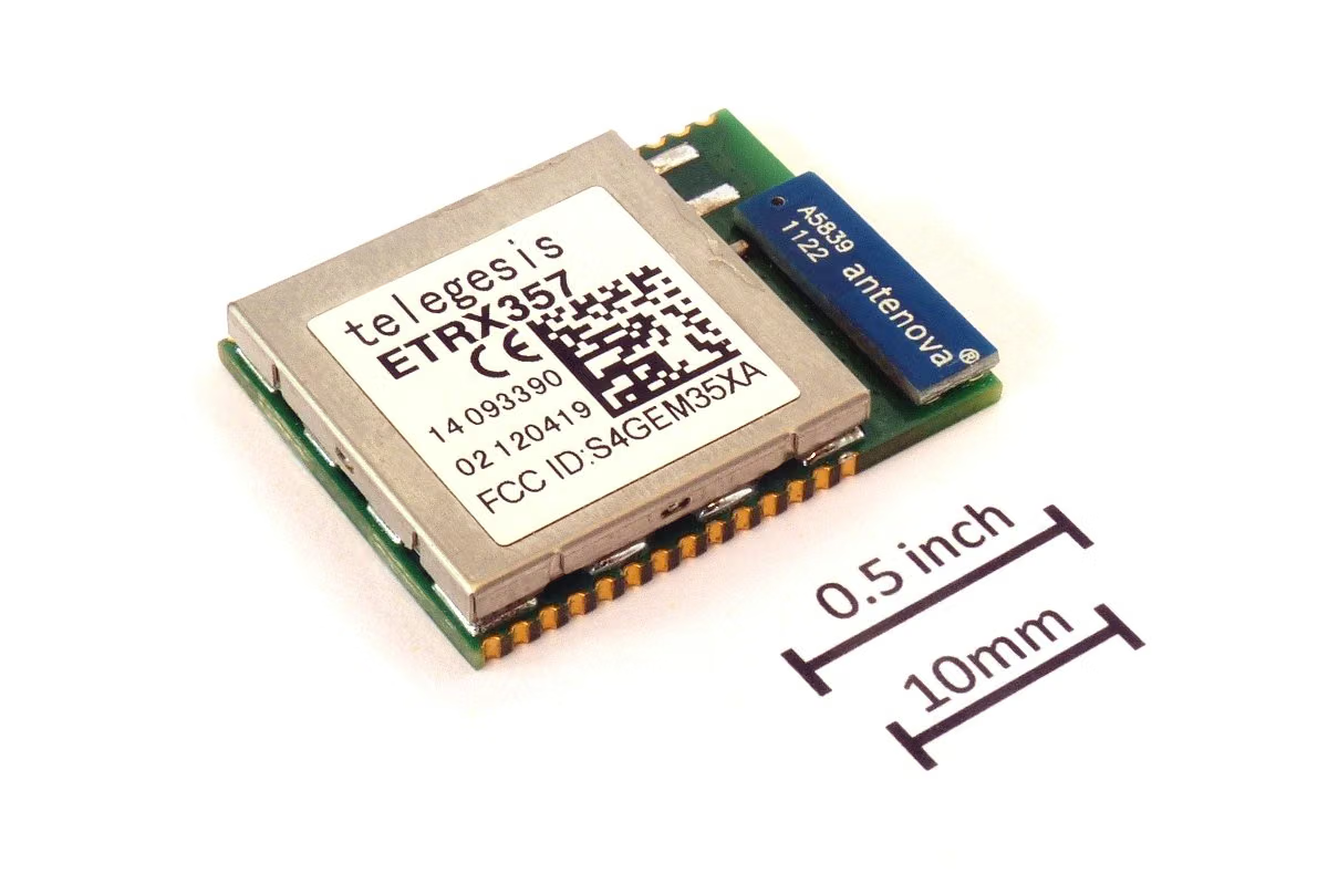
- IoT module antennas
In Which Sectors Is Antenna Tests Used?
Standards Related to Antenna Tests
- IEEE Std 149
- CTIA OTA Test Plan
- IEC 61169 (fasteners)
- 3GPP TR 37.977 (MIMO OTA)
Antenna Tests Conditions
- Quantities measured
- Return loss/VSWR, gain, total radiation efficiency, radiation pattern, polarization
- Measurement environment
- Reflective room; far field or conversion from near field to far field
- Frequency range
- Bands covered by the application
- Positioning
- Defined angle steps in global scanning
Equipment for Antenna Tests
- Anti-glare antenna measuring chamber
- Vector network analyzer
- Global positioner and reference antenna set
- Near field scanning system
Sample Requirements for Antenna Tests
- Antenna or device must be in final configuration
- Supply cable and connector losses must be documented
- Device body and user impact scenarios must be defined
- Reference antenna calibration must be traceable
Duration of Antenna Tests
Typically 1–2 weeks depending on tape and scan resolution.
Antenna Tests Procedure
- 1The antenna is installed on the measurement device.
- 2Return loss and impedance are measured.
- 3The global radiation pattern is scanned.
- 4Gain and total radiant efficiency are calculated.
- 5The polarization characteristic is determined.
- 6The results are compared to the design requirement.
Antenna Tests Acceptance Criteria
Acceptance criteria are given as gain, efficiency and VSWR targets in the product design specification.
Evaluation of Results
Antenna performance is strongly dependent on the housing in which it is placed; Individual antenna measurement does not represent in-device performance. The total radiant efficiency measurement on the device should be taken as basis.
Antenna Tests Report
- Applied measurement method
- Antenna and device description
- Measuring environment and calibration
- Earnings, yield and pattern results
- Measurement uncertainty
Accreditation
EUROLAB holds internationally recognised accreditation obtained from accreditation bodies party to the IAF and ILAC multilateral recognition arrangements, under ISO/IEC 17025 for laboratory testing, ISO/IEC 17020 for inspection and surveillance, and ISO/IEC 17021-1 and ISO/IEC 17065 for system and product certification. This chain ensures the reports and certificates issued are accepted worldwide.
Whether this test can be offered within accredited scope depends on your product and the standard applied; since accreditation is method-based, the scope is confirmed in writing at the quotation stage.
Scope and authorisationsRelated Regulations
- Product design specifications
- Carrier OTA requirements
RF and Wireless Testing — What Does This Testing Field Cover?
The section below describes the field that the Antenna Tests test belongs to; the conditions and acceptance criteria of this particular test are given in the sections above. The scope specific to your product is confirmed in writing at the quotation stage.
RF and wireless testing shows that a device containing a radio uses the spectrum correctly and operates within the limits the relevant legislation allows. This family is a separate body of work from EMC: EMC addresses unwanted interference, whereas here INTENTIONAL emission is assessed.
Spectrum is a public and limited resource, and this determines the legal character of the field. A device spilling outside its permitted band or emitting excess power is not merely a technical defect but a violation that disrupts someone else's service. Radio conformity is therefore policed more strictly than other test fields and markets maintain their own national regimes.
Measurements run separately on the transmitter and receiver sides. On the transmitter side, output power, occupied bandwidth, frequency error, unwanted emissions, adjacent channel power and the power envelope are measured. On the receiver side, sensitivity, selectivity, blocking and spurious response rejection are assessed. The receiver side is often neglected, but in some bands it is a regulatory requirement.
Access protocol specific behaviours are a third axis: listen before talk (LBT), duty cycle, dynamic frequency selection (DFS) and transmit power control (TPC). These mechanisms enable spectrum sharing and it must be shown that they work correctly.
HUMAN EXPOSURE is the fourth axis and one of the most commercially critical. For devices used close to the body, SAR (specific absorption rate) is measured; for devices used at a distance, a field strength assessment is made. Limits and measurement methods vary by market; the same device is assessed separately for Europe and the United States.
Market regimes are decisive in this family and do not substitute for one another: the Radio Equipment Directive and ETSI harmonised standards in Europe, FCC authorisation in the United States (through a TCB for intentional radiators), ISED in Canada, MIC in Japan, KC in South Korea and SRRC in China each carry their own set of requirements. The same device requires a separate file for each market, and some markets impose a local representative or local testing requirement.
Module integration is the subject that raises the most questions in the field. Using a certified radio module does not automatically make the device compliant. A module certificate is valid for a defined antenna, a defined supply and defined conditions of use; if the antenna changes, the layout changes or the module is operated at a different power level, reassessment is required.
The presence of several radios in the same device (Wi-Fi + Bluetooth + cellular + NFC) gives rise to a simultaneous transmission assessment: SAR and unwanted emission measurements are made for the worst case in which the radios operate together.
Method groups in this field
Transmitter measurements
Output power, occupied bandwidth, frequency error, unwanted emissions, adjacent channel power, power spectral density.
Receiver measurements
Sensitivity, selectivity, blocking, spurious response rejection.
Spectrum sharing mechanisms
Verification of listen before talk, duty cycle, dynamic frequency selection and transmit power control.
Human exposure
SAR measurement (handheld and body-worn devices), field strength assessment, multi-radio scenarios.
Protocol conformity
Cellular network conformity testing, Bluetooth and Wi-Fi certification testing, GNSS performance.
Antenna measurements
Gain, radiation pattern, efficiency and total radiated power (TRP) measurements.
Commonly confused in this field
- Using a certified module does not automatically make the device compliant; if the antenna, layout or power level changes, reassessment is required.
- An FCC file does not replace a CE file; each market operates its own regime.
- Receiver side measurements are a regulatory requirement in some bands; measuring only the transmitter produces an incomplete file.
- SAR limits and measurement methods differ by market; a result in one market does not carry over to another.
- For devices carrying several radios the simultaneous transmission scenario must be assessed; measuring them individually is not sufficient.
- Some markets impose local testing or a local representative requirement; technical conformity alone does not secure market access.
Which decisions these results support
- Market access under radio equipment legislation
- Verification of the antenna and RF front end design
- SAR and RF exposure conformity
- Verification of module integration and the scope of reassessment
- Determining the worst case in multi-radio scenarios
Related Tests

Frequently Asked Questions About Antenna Tests
According to which standard is Antenna Tests made?
Antenna Tests is executed in scope IEEE Std 149, CTIA OTA Test Plan, IEC 61169 (fasteners) and 3GPP TR 37.977 (MIMO OTA). The limit values and acceptance criteria to be applied are defined in the product standard; The version valid for your product is confirmed in writing at the offer stage.
Which products does Antenna Tests apply to?
Mainly applied to Integrated antennas within the device, External and on-board antennas, Base station and access point antennas and IoT module antennas. Whether your product is included in the scope is determined by examining its technical specifications and intended use.
Under what conditions is Antenna Tests done?
The determining parameters are: Quantities measured — Return loss/VSWR, gain, total radiation efficiency, radiation pattern, polarization, Measurement environment — Reflective room; far field or conversion from near field to far field and Frequency range — Bands covered by the application. The full terms are in the "Test Conditions" section on the page and vary depending on the product standard.
What kind of sample is needed for Antenna Tests?
Antenna or device must be in final configuration, Supply cable and connector losses must be documented and Device body and user impact scenarios must be defined. The number of samples is determined according to the product standard and the scope to be reported.
How long does Antenna Tests take?
Typically 1–2 weeks depending on tape and scan resolution. This duration belongs to the experiment itself; sample preparation, queuing and reporting are also evaluated. A realistic schedule for your product is given in the offer.
What is the Antenna Tests result called "appropriate"?
Acceptance criteria are given as gain, efficiency and VSWR targets in the product design specification.